ACISS: 創薬支援in silicoサービス
Affinity-Constella In Silico Support
ACISS (Affinity-Constella In Silico Support)サービスは、創薬やその他関連分野における計算科学支援を目的として、(株)アフィニティサイエンス、(株)理論創薬研究所と(株)インテージヘルスケアが共同で提供する受託研究・解析サービスです。各種インシリコスクリーニング、シミュレーションによる検証、化合物DB整備、最適なソフトウェア・システム導入など、優れた費用対効果でトータルに創薬研究をサポートします。
【コア技術】
CGBVS(Chemical Genomics-Based Virtual Screening):相互作用マシンラーニング法
PBVS(Pharmacophore-Based Virtual Screening):ファーマコフォアベース法
SBVS(Structure-Based Virtual Screening):ドッキングシミュレーション法
LBVS(Ligand-Based Virtual Screening):類似化合物探索法
CGBVS(相互作用マシンラーニング法)
既知相互作用情報を機械学習することにより、未知のタンパク-リガンドペアの相互作用を予測する、独自の計算手法です。化合物探索以外に、標的予測計算や化合物デザインへの応用が可能です。
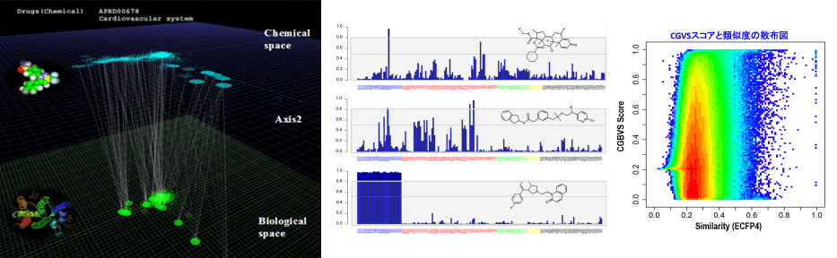
※CGBVSは、京都大学の特許技術として実用化されたものです。受託計算での実績の他、システム提供、スーパーコンピュータ「京」での実施例など多くの実績があります。
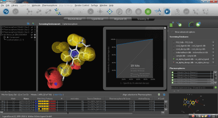
PBVS(ファーマコフォアベース法)
活性化合物の官能基特性を三次元配座で表わしたファーマコフォアモデルを構築し、新規化合物の探索に用います。既知活性化合物の高速・高精度配座解析(リガンドベース)、あるいは複合体の活性コンフォメーションの利用(構造ベース)、いずれかの方法でファーマコフォアモデルを構築します。
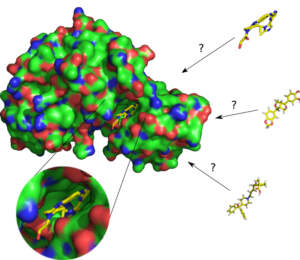
SBVS(ドッキングシミュレーション法)
標的タンパク質の立体構造モデルを用いたシミュレーションにより、活性ポケットに結合する化合物を探索します。
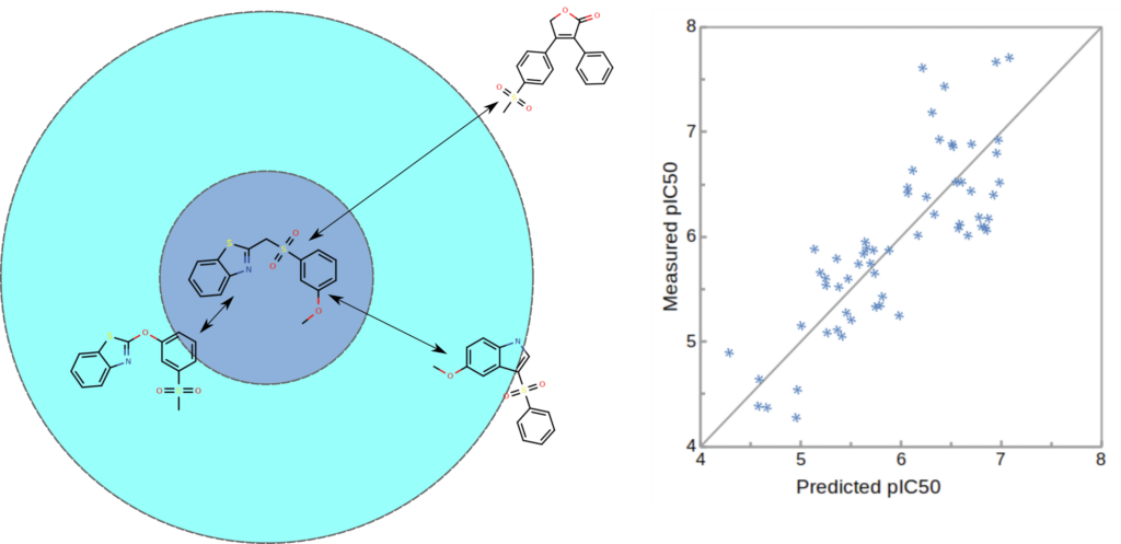
LBVS(類似化合物探索法)
分子構造や物性に基づいて既知の活性化合物に類似する化合物を探索します。
創薬プロセスにおける計算活用例
各計算手法に必要な条件と結果の特徴
| 手法 | 計算に必要な条件・データなど | 得られる結果の特徴 |
|---|---|---|
| CGBVS:相互作用マシンラーニング法 | 標的タンパク質の一次配列情報既知活性、不活性化合物の情報 例)IC50<30μMのリガンドデータ100個標的タンパク質の周辺(類縁)タンパク質の既知活性情報も有効に活用できる | 膨大な既知データの機械学習によるパターン認識に基づいて相互作用を予測する既知構造の周辺化合物の探索に有効新規構造化合物の探索に有効標的タンパク質予測にも応用が可能 |
| PBVS:ファーマコフォアベース法 | リガンドベース構築の場合:既知活性化合物の情報(数個程度)構造ベース構築の場合:標的タンパク質とリガンドの共結晶構造(PDB) | 活性化合物から三次元配座モデルを作成してスクリーニングに用い新規構造の化合物もヒットする可能性がある標的タンパク質が不明の場合も実施可能(⇒リガンドベース構築) |
| SBVS:ドッキングシミュレーション法 | 標的タンパク質の立体構造(PDB)既知化合物との共結晶構造が望ましい | 標的タンパク質のポケットと化合物の結合様式をシミュレートする新規構造の化合物の探索に有効 |
| LBVS:類似化合物探索法 | 既知活性化合物の情報(数個~)標的タンパク質が明確でない場合も有効 | 既知活性化合物に対する類似性を指標として化合物を探索する既知化合物の周辺構造の探索に有効新規構造の化合物の探索には不向き |
計算手法の特徴比較表
| 比較項目 | CGBVS | PBVS | SBVS | LBVS |
|---|---|---|---|---|
| タンパク立体構造 | 不要 | あれば利用可能 | 必要 | 不要 |
| 標的タンパクの既知化合物情報 | ある程度必要 | 必要 | ある程度必要 | 必要 |
| 標的周辺(ファミリータンパク)の既知化合物情報 | ある程度必要 | 不要 | 不要 | 不要 |
| 予測精度 | ◎ | ○ | △ | ◎ |
| 新規化合物探索能 | ◎ | ○ | ◎ | △ |
| 速度・計算コスト | ◎ | ○ | △ | ◎ |
| 化合物最適化への応用 | ○ | ○ | ◎ | △ |
| 標的予測への応用 | ○ | ○ | × | ○ |
(各手法について、おおまかな特徴をまとめたものです。検討条件によっても変わる場合がありますので、個々の詳細についてはお問い合せ下さい。)
スクリーニング対象ライブラリについて
弊社スクリーニングの対象化合物としては下記があります。
- 依頼企業が保有する内部ライブラリ(数万~10数万化合物)
- 市販の化合物ライブラリ(ナミキ商事(株)、キシダ化学(株)など)
(ナミキ商事化合物の実施例)
→ ナミキ商事全在庫品(500万化合物)
→ 主要3サプライヤ限定(200万化合物)
→ 短納期サプライヤ限定(250万化合物~) 納期1~1.5ヶ月程度
→ バーチャルライブラリ(400万化合物)合成率85%以上
など